T2Laser
What is T2Laser?
-- A replacement software controller for Benbox style laser engraving systems and other laser or CNC systems using Grbl firmware or requiring G-Code
Key Features
-- Image to G-Code Conversion
- Supports JPEG, BMP, PNG and GIF import
- Greyscale (S-value) and 1-Bit (dithered or threshold) conversion
- Velocity mode uses variable feed rates to produce greyscale
- CNC mode for 3D milling (Z-axis) or Laser Z-axis focusing
- Advanced raster-to-vector conversion with optional automatic hatch fill
- Resolution is user configurable
- Horizontal or diagonal engraving (45 degree engraving makes lines less visible)
- Skip "blank" lines (improves engraving speed by eliminating unnecessary moves)
- Image resize (uses an optimized algorithm to improve quality)
- Provides image adjustments (brightness, contrast, flip and rotation)
- G-Code can be saved (registered users only)
- Profiles are available to store and recall common settings
-- DXF and PLT Import
- Supports DXF/PLT import with colors translated to laser power or feed rates
- Multi-pass cutting for thicker materials (with optional cool down between repeats)
- Path optimization to reduce time and improve efficiency
- Adjust power or feed rate in each axis independently
- Vector resize, rotate and flip
- Use DXF colors to determine cutting sequence
- Output each color individually or sequentially with tool changes as needed (swap CNC bit or pen)
- Optional PDF conversion using an open source 3rd party utility
-- Gerber Import
- Load Standard (RS-274-D) and Extended (RS-274-X) Gerber files
- Aperture, Region and Drill Files are supported
-- Sketch and Trace (Raster to Vector)
- Create quick sketches using basic tools and text (includes arc text)
- Output as vector, hatch or raster (filled)
- Combine Sketch with image (add raster text or a vector path)
- Combine Trace vector (contour cut) with image
-- Laser Control
- Supports Grbl or Benbox firmware (S, L or P values can be used for laser power)
- PWM available with Grbl 0.9 or higher firmware and compatible hardware
- Upload firmware and default settings (no additional files or programs required)
- Load and edit G-Code files - supports raster and vector formats (registered users only)
- User interface for jogging (8-way) with step distance and set / return home
- Homing is supported with appropriate hardware
- Machine and workpiece position readouts, position presets for loading or jig positions
- Estimated time is displayed and progress bar / buffer state is shown when sending
- Laser on, off and pulse (using user configured power and time)
- Real-time laser and feed rate overrides available in Grbl 1.1 and higher
- Supports Dynamic Laser Power to prevent over burning due to acceleration
- Debug and Check modes are supported to verify G-Code before sending
- Emergency stop and fail safe error handling
- G-Code sender is optimized for small segments and constant power / feed adjustment
- Tested with files containing -7,000,000 lines of G-Code (trial is limited to 10,000 lines)
-- G-Code Viewer
- Supports laser power and variable feed rates for true representation of result
- Identify problems before sending to the laser
- Shows home and frame positions
- Run the G-code in the simulation to check cutting sequence
Installation
-- Download the latest T2Laser_Installer zip file
- If you are upgrading a version pre-1.4d, first uninstall using control panel (if registered, this will not affect your license key)
- Version 1.4d and later use web deployment and you will be notified of upgrades automatically (if connected to the internet)
-- Open the zip and review the end user license agreement (EULA)
- After acceptance of the license agreement, run setup.exe
- If needed, T2Laser can be uninstalled using the control panel
Laser Safety
- Always wear protective eyeglasses that are rated for the correct wavelength when the machine is powered on (the laser may energize unexpectedly)
- Do not leave the machine unattended while operating, if communications are interrupted the machine could stop with the laser on causing damage or fire
- Disable power saving modes (BIOS and/or OS), anti-virus and backup software that could affect normal operation
- Verify that materials being engraved or cut are "laser safe" and do not produce harmful vapors and also maintain adequate ventilation
Main Window
(Design Screen)
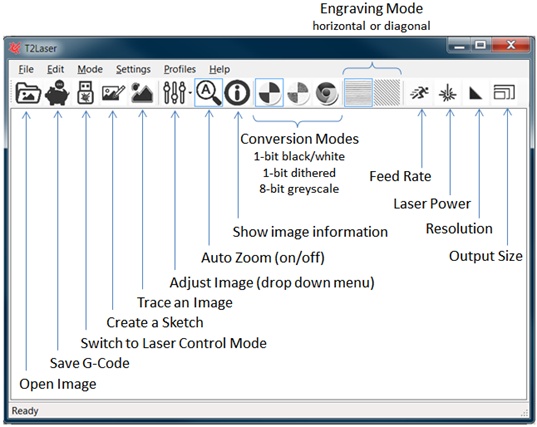
-- Open Image
- Load a raster image (JPG, BMP, PNG or GIF)
- Right click to import a vector in AutoCAD DXF or HPGL PLT format (see Vector Import section)
-- Save G-Code
- Processes the image and saves the G-Code file
-- Control Laser
- Switches to the laser control screen
-- Sketch
- Create a raster or vector drawing (see Sketch section)
- Right click to load a Sketch or Sketch Template file
-- Trace Image
- Raster-to-Vector conversion of the loaded image (see Trace section)
- Auto Trace can be used to convert the entire image
-- Edit Image
- Brightness, contrast and gamma adjustment
- Rotate image clockwise or counter-clockwise
- Flip the image (useful for back engraving mirrors)
- Invert the image (produce a negative image)
-- Auto Zoom
- z key toggles on/off
- 100% (actual view)
- Zoom to fit window
-- Show Image Information
- i key toggles on/off
- Displays the image size in pixels and millimeters
- Shows DXF extents, count of line segments and shapes
-- Image to G-Code Conversion Mode
- 1-bit black and white (best for text or drawings)
- Dithered (Floyd Steinberg diffusion method), pixels are black or white (min or max power)
- Greyscale (Laser power changes based on pixel value, black represents maximum power)
- Click on image to show original (color if applicable)
-- Engraving Mode
- Horizontal (lines are scanned along the X-axis)
- Diagonal (scans using X and Y simultaneously, eliminates "screen door effect")
-- Feed Rate
- Sets the default engraving speed
- Right click to set the rapid feed rate (speed when laser is off)
-- Laser Power
- Sets the minimum and maximum laser power values
- Default 0-255 but can be changed for different configurations
-- Resolution
- Sets the output line resolution for image conversion
- 0.1 mm line resolution = 10 lines per mm or 254 DPI
- Lower values will have a higher resolution but take longer to process
- Determines the auto-join gap for DXF segments
-- Output Size
- Sets the output dimensions for raster images
- Can also be used to re-scale vector data (it is recommended to set the correct size in your CAD program before exporting)
- Image is resized (uses an optimized algorithm to improve quality)
- It is recommended to set resolution before output size
-- Additional Menu Items (not available on the toolbar)
- File
- Import GBR
o Loads Standard (RS-274-D) or Extended (RS-274-X) Gerber files
o Set the resolution before importing
o The drawing is loaded as an image and can be processed using the edit image tools
o Standard format requires an aperture file (.APT) in the same directory with either the same name or prefix as the Gerber file
o Drill files (.DRL) with either the same name or prefix as the Gerber file in the same directory can be overlayed (negative)
- Convert PDF
o Converts Adobe PDF files to AutoCAD DXF format and loads the vector data in T2Laser
o Requires installation of the optional Convert2DxfCmd application developed by Agastar on the benboxlaser.us forum
- Sketch Template
o Loads a T2Laser Sketch Template
- Clear
o Image, Sketch and/or Vector data is deleted
- Edit
- Auto Trace...
o Converts the entire image from Raster-to-Vector
- Crop Image
o Select a portion of the loaded image
- Mode
- Photo Mode
o Uses a pixel shifting algorithm (similar to anti-aliasing) to blend the grey levels for a more natural look.
o Produces a "softer" image (not recommended for clip art)
o This algorithm will be used if a suitable image is detected and does not normally need to be manually selected
- Velocity Mode
o Uses variable feed rate to produce a greyscale result
o Rapid and standard feed rates must be set correctly
- Sketch (Filled)
o Sketch is created as a raster image (text or shapes will be filled)
o See the Sketch section for examples and additional details of use
- Sketch (Hatch)
o Sketch is created as a vector with pseudo fill using lines
o See the Sketch Hatch section for examples and additional details of use
- Sketch Plus (Overlay)
o Combines raster or vector Sketch with the loaded raster image
o Allows contour cutting or adding text to an image
o See the Sketch section for examples and additional details of use
- Settings
- Multi-Pass (Vector)
o Repeats the vector path multiple times to enable cutting of thicker materials
o Pre-defined or custom repeats (unlimited)
- Cool Down Delay
o Used with above option to dwell after each pass for laser to cool down
- Matrix Copy (Sketch)
o Generates Step and Repeats for Sketch drawings
o Set parameters for columns (X), rows (Y) and gap (spacing in mm)
o Note: You must disable multi-pass and select lower left start position
- Center (Start Point)
o Position the laser (and set home) in the center of the job (between extents) before starting
o Absolute option uses the entire drawing from 0,0 to maximum extents for center position
- Corner (Start Point)
o Lower left start is the default location, lower right, upper left and upper right are options
o Position the laser (and set home) at the corner of the job before starting
o This option can be used with Gerber files to enable back side alignment
- Use Extents for Frame
o Force the frame to use drawing extents (instead of including 0,0)
- Skip Blank Lines (default)
o Speeds up engraving by skipping blank areas within the job
- Laser (Z-Axis Focus)
o Use S values for laser power but enables manual Z-jog controls
- CNC Mode (Z-Axis)
o Use Z-Axis values
o Enter the maximum Z-depth
o Top of material is defined as Z0 (typically with positive values down)
o Optionally enable depth per passes (Z-depth will be divided equally between each multi-pass)
o Optionally set a Z-safe height (typically a negative value)
o Set a spindle speed (max is usually 255 or 1000 depending on firmware)
o Optionally set a spindle delay in seconds (allows the spindle to get up to speed)
- Threshold (B/W)
o Sets the pixel threshold for 1-bit black and white conversion
o Transparency is converted to white (laser off)
- Image Options
- Bi-Directional Scanning (default)
o Horizontal scan mode follows a serpentine pattern
o Disabling will scan left to right only
- Rapid Skip Blank
o Use the rapid feed rate in blank areas (faster)
- Skip Solid Lines
o Used only for CNC systems or special purposes
- Over-Scan
o Forces laser to remain on during horizontal line transition
o Likely to produce a darker edge to the image
- Transparency to White
o Used with PNG files. Any transparent region is converted to white (or black if unchecked)
- Trace Resize (Single Mode)
o When enabled (default) the Trace resolution is maintained when scaling for improved detail
o Disable to reduce the path which will lose some detail but may improve engraving speed
- Eliminate (Trace) Noise
o Removes objects smaller than 5mm² (clean up result but may lose some fine detail)
- DXF Options (note: options marked with * only have an effect at load)
- Relocate Origin (works with vector files and Trace feature)
o The origin (0,0) is set at the minimum drawing extents
- DXF Optimizer (also works with PLT files)
o Changes the sequence of vector segments and paths to reduce run-time
o Options to override start point and/or allow segment reversal
o Can also force auto-joining of open shapes (this may distort the file, check the view before using)
o Use DXF colors to determine cutting sequence (Yellow, Green, Blue, Orange, Red and Black)
- Override DXF Units*
o If checked, values are used as metric and header is ignored (no conversion)
o Option to force conversion (header is ignored, values are treated as inch units)
- Select Output Color
o All (default) sends all colors with their corresponding power values in the order generated
o Sequential sends each color in series using reverse order (5=Yellow, 4=Green, 3=Blue, 2=Orange, 1=Red and 0=Black)
o Select an individual color to send only that color
o Sequential and Individual colors default to max laser power unless Use Power Value is selected
- DXF Color to Feed Rate
o Adjusts the feed rate (instead of laser power) based on DXF color, works with non-PWM laser modules
o Black (Feed Rate), Red, Orange, Blue, Green and Yellow (Rapid Feed Rate)
- Absolute DXF Colors
o Uses an absolute percentage of the power or feed rate based on color (method used in earlier version)
o Black 100%, Red 80%, Orange 60%, Blue 40%, Green 20% and Yellow 0% (increment percentage can be changed)
- Vector Adjustment
o Linearly increases power or feed rate based on the vector (angle) of motion
o Swap XY changes the vector (default is lower power or higher feed rate in X-axis)
o Set percentage value to adjust (e.g. add 20% to the feed rate or power when perpendicular to the axis)
- Ignore Bulges*
o When enabled the bulge parameter is ignored (converted to straight lines)
- Reverse DXF Paths*
o Set before import to reverse the path direction
o Typical paths are engraved counter clockwise with this option disabled
- Reverse DXF Segments (default)*
o Each segment within the DXF path is reversed (necessary for some software)
- Skip Minimum Power
o When selected any minimum power (yellow) segments will be skipped (default)
- Advanced Settings
- Silent Mode
o Does not ask to generate or save G-code (defaults to Yes and No respectively)
- Auto-Crop Sketch
o When selected the Sketch will automatically be cropped to extents when generating the G-code
o Use the manual crop (Resize Canvas) option in Sketch if you want to adjust or add a border
- Skip Sketch Template
o When selected a Sketch Template will only output the user editable objects
- End Program (M30)
o Issues a G-Code end program command after the job completes
o This is necessary on some systems to completely disable the laser
o Workpiece home position will be lost (recommend setting machine home)
- Gerber Options
o Set the units and accuracy for Gerber files (only required if header information is unavailable)
o Additional settings to ignore aperture data or use drill files
- Hatch Options
o Use Vertical, Diagonal lines (right click to change from / to \) or Cross Hatch (right click to change from x to +)
o Change the spacing between lines; narrow, default, wide or custom
o Exclude the outline so only the fill is engraved
- Anti-Alias Display
o Helps reduce moiré patterns on computer screen only, does not affect output
- Keep Display On
o Forces your display to remain on while T2Laser is running
- Insomnia Mode
o Prevents your computer from sleeping (can be temporarily disabled but will reset to on at startup)
- Disable Image Adjustment
o When selected Image Adjustments will be disabled (e.g. brightness, contrast, flip and rotation)
o Enable when using very large images to reduce memory and resource usage
- Splash Screen
o When enabled a T2Laser or corporate partner logo will be displayed at start-up
o Option 0 will load a random background, other values load the specified image
- Profiles
- Click to load a preset profile
o Includes feed rate, min/max laser power, resolution, passes and cool down
- Set parameters and then right click on the profile to edit the name and save settings
o Previous settings will be overwritten
- Profile Management
o Backup or restore profiles (save to a text file)
- Help
- About
o Shows version number
o Register the trial version (see the Register section for more details)
- Manual
o This document
- YouTube Channel
o Videos explaining the basic operation of T2Laser
- Samples
o Built-in files which can be used to test your machine
- Change Language
o Used to override the automatic language selection (temporarily)
o Deselect the "Automatic" selection to permanently use the manual selection
- Restore Defaults
o Resets the user settings to their default values
- Security Dongle
o Use a hardware security device for license verification
- Install CH340 Driver
o This installs the USB-to-Serial COM driver for the CH340 chipset
- Check for Updates
o This is for beta testers only (pre-release versions) and requires a password to install
o You will be notified automatically when a new release is available (must be connected to the internet)
Laser Control
Window (shown connected)
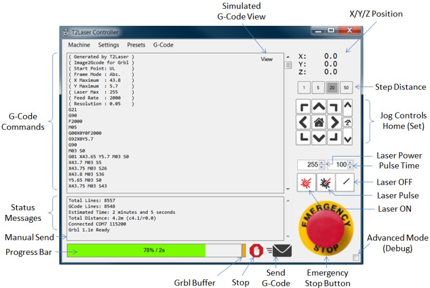
-- Connect Settings
- Select Port and Baud Rate
- Click the lightning bolt or select Connect in the Machine menu to connect
- If no ports are shown check connection and click lightning bolt to re-scan
- USB driver for your device must be installed
- Once the COM port is open the status message "Connected" will be displayed
- If the Grbl firmware begins communication the message "Grbl Ready" will be displayed (the version may also be displayed)
- If Benbox firmware is detected the message "Benbox Ready" will be displayed
-- Firmware Upload
- Select COM port and click Upload Firmware (x.x) from the Machine menu
- 1.1e (default) includes support for homing on D9 and dynamic laser power [enable in the Settings / Advanced menu]
- 0.9g J-Tech. Supports most systems, uses 7.8KHz PWM [once installed use 'Send Default Parameters' to load T2Laser default values]
- 0.9i EleksMana. Use for EleksDraw or EleksEgg systems that require either Servo or CoreXY control (see sub menu for configuration)
- 0.9j Woodpecker. For use with their CNC controller boards
- 1.1e Non-PWM. Uses D12 for the laser, not officially supported [automatically enabled in the Settings / Advanced menu]
- 1.1e Axis Swap. Same as default except X and Y axis are swapped
- 1.1f LaserAxe. Uses custom pin outs for some of their machines (others can use the default firmware)
- 1.1f High Frequency PWM. Uses 7.8kHz instead of the standard 1kHz PWM
- Alternative method; Disconnect your machine (right click the stop button) or select Disconnect from the Machine menu, then select COM port and Ctrl-Click the lightning bolt to upload Grbl 0.9 laser firmware. There should not be any G-Code loaded in the command window
-- Grbl Parameter Upload
- Ctrl-Click the Send G-Code (envelope) or select Send Default Parameters from the Machine menu to upload the default parameters
- Check the status messages to confirm parameters were uploaded correctly, repeat as needed
-- G-Code Commands
- This window displays the current program
- Double click the window or click Load G-Code from the Machine menu to load a G-Code (.nc) program file
- When disconnected from the laser, G-Code can be edited
-- Status Messages
- Important system messages and responses from Grbl are shown here
- Double click to clear the status messages
-- X/Y Positions
- After connecting the current X/Y (Z) positions are displayed
- Double click to switch between machine and workpiece positions or select Machine Coordinates from the Settings menu
- Machine positions are shown as *X and *Y (*Z)
- If machine is moving the positions are displayed in red
-- Step Distance
- Select the distance to be moved during a manual jog (mm)
-- Home (Origin)
- Click to return to the workpiece home position (not the machine origin)
- Right click the home icon or select Set Origin (Workpiece) from the Machine menu to set workpiece home position (a soft reset clears the workpiece home position)
- If Machine Coordinates are displayed, right clicking will request to run the Home (Machine) procedure, if you select no the Set Origin (Workpiece) command will run
-- Home (Machine)
- Typically used with home/limit switches (Grbl must be manually configured for your setup)
- If home switches are not enabled this sets the persistent machine offset
- Enable homing with the Home Switches option in the Settings menu
- Select Home (Machine) from the Machine menu to start the homing procedure or set the machine offset
- If Reset Workpiece Origin is selected in the Settings menu the machine offset will be set once homing is complete
-- Jog Buttons
- Move (step distance) in the direction selected
- If Z-Axis Focus or CNC Mode are selected the Z jog keys will be available
- Cursor keys (arrows) work when step is set at 20 or less, home key goes to workpiece origin
-- Laser Power
- Select the laser power from 0-255 used for manual laser operation
-- Pulse Time
- Select the manual laser pulse time in milliseconds
-- Manual Laser Controls
- Switch the laser on using the power setting specified above
- Pulse the laser using the power and pulse time specified above
- Switch the laser off
-- Send G-Code (start the program)
- Click the envelope or select Send G-Code from the Machine menu to begin sending the loaded G-Code to the machine
- While running, click to pause and again to resume or restart the G-Code program
- Commands already in the Grbl buffer will be processed before the machine halts
- If a tool change is required, sending will pause until you confirm the change was completed (do not click OK until clear of the machine)
-- Stop Button
- G-Code sending is halted, after a few seconds the machine will stop
- The laser will be turned off
- The machine will return to workpiece home
-- Emergency Stop (left click)
- Soft reset, the machine will come to a controlled stop
- The laser will be turned off
- Workpiece home will be cleared
- Current XY position will be maintained
- ESC key performs the same function
-- Emergency Stop (right click)
- Right click the stop button to perform an immediate (emergency) stop
- The laser will be turned off and the connection terminated
- XY positions may be inaccurate (if the machine is moving some steps can be lost)
-- Progress Bar
- Shows the transfer progress as the G-Code file is processed
- The far right block shows the Grbl buffer status
- During transfer it should flash red (full) to orange (almost full)
-- Debug Mode
- Click to enable or select Advanced Mode from the Settings menu
- The manual G-Code command box is displayed
o Enter commands and click enter to send (used to change Grbl parameters)
- Additional messages are displayed in the status window during communication
- This should be disabled when not required to maximize performance
-- Rotary Axis
- Click to enable (opens the setup page) or disable
- Right click to change the settings without disabling
- First time setup (settings are stored)
- Select the axis you are replacing
- If the rotary axis is opposite to your standard axis, select the reverse check box
- Enter the steps per rotation using the formula shown (motor steps per rev * micro-stepping * drive ratio)
- Your original values are automatically stored and should not need to be changed (these are used when rotary axis is disabled)
- Enter the item diameter or circumference
- The calculated steps per mm will be displayed in the pending changes section, click OK to send these changes to your Nano
-- Presets
- These user presets store the machine and workpiece coordinates
- Click to recall the preset and move to the location specified
- Right click to save the current positions (optionally enter a name)
- If Use Machine Positions is selected (default) the stored machine coordinates are used
-- Advanced Features
- Disconnect machine
- Right click the Stop button to disconnect.
- Sleep Mode
- If using Grbl 1.x or later and motor are always energized you can use place the machine in a sleep mode, clicking again wakes the machine
- Display Grbl Parameters
- Ctrl-Click the Home button or select Display Grbl Parameters from the Machine menu to download/view Grbl parameters
- Reset Grbl Parameters
- Restores all $ values to the original firmware settings (these are the T2Laser defaults if using v1.x firmware)
- Clear Grbl Positions
- Clears all stored positions (if your coordinate display is not showing 0,0 after connecting this will clear the offset)
- Reverse Axis Directions
- Use the Reverse X/Y/Z-Axis Direction options in the Settings menu
- Z Axis Jog Control
- Enabled the Z axis jog buttons (option to reverse the jog key directions)
- Laser Power Override
- Right click the laser power value or select Override Laser Power from the Machine menu to override laser power in loaded G-Code file
- The values will be rescaled using the selected value as maximum (based on 255 as maximum or 100%)
- Right click power value and select no to cancel override and return to original values
- Feed Rate Override
- Right click pulse time value or select Override Feed Rate from the Machine menu to override the feed rate in the loaded G-Code file
- Enter a new value and click OK, or select cancel to cancel the override
- Real-Time Feed Rate and Laser Power Override (only available with Grbl 1.x or above)
- When running the override options will be displayed
- Click + or - to change the override percentage or click 100% to return to G-code values
- Feed rate can be set between 10% and 200%, Power between 50% and 200%
- Draw the frame / border (for alignment)
- Right click the laser on button or select Engrave Frame from the Machine menu to laser the frame at the specified power level
- Right click the laser off button or select Trace Frame from the Machine menu to trace the frame with the laser off
- Check Mode
- When enabled G-Code is parsed by Grbl but not sent to the laser, this is used to check the code for any errors before starting the job
- Post Processors
- Grbl (default), uses S values for laser power control
- Benbox compatible G-code
- LaserBot mode uses P values for laser power (this is experimental and still in development)
- Laser D12 (used with the non-PWM firmware on older hardware that does not support D11 laser signals)
- Configure EleksMana (only for use with the EleksMana firmware)
- Click to select your machine; Laser, Draw, Egg or Mill
- Click to change modes; Laser, Servo, Cartesian or CoreXY
- Advanced
- Dynamic Laser Power, adjusts laser output based on feed rate to prevent over-burning at the start and end of lines or dots at corners
- Estimated Time Remaining, displays the ETR in the progress bar during send (this is approximate)
- Alternate Jog Increments, use reduced (1/10th) values for jog distances (right click on jog buttons to switch mode)
- Display Custom Buttons to run user editable G-code. Right click to enter the name and commands (use | to indicate line breaks)
- When Jog Rapid Feed is enabled, jogging will use the rapid feed rate instead of machine maximum speed as determined by Grbl parameters
- When Frame Rapid Feed is checked rapid feed rate will be used instead of vector feed rate for Engrave and Trace Frame
- Hold Position keeps the motors energized to prevent accidental movement but may cause overheating and failure of the motor or driver
- Fast Status increases the coordinate refresh rate (X5) but can overload the microprocessor
- Reduced Acceleration, use slower ramp rates to minimize backlash and/or lost steps on systems which are not mechanically optimized
- Machine Size uploads the default machine size set in Sketch to the Grbl parameters. This is only required if you have home or limit switches
- If selected DTR sets the Data Terminal Ready pin (default)
- Fail-Safe Mode (attempts to disable the laser if any errors are detected)
- Low Buffer Mode, reduces the Grbl buffer (for diagnostic purposes only)
- Laser Mode, should be enabled for lasers (even if they have a Z-axis) and disabled for CNC machines using a spindle
- Clean G-Code (Aggressive), this may fix imported G-code errors (Note: Use caution as G-code may be corrupted)
-- View
- Display a simulation of the G-Code
- Laser power is shown from yellow to blue (max power)
- Press ‘o’ to show laser off as yellow
- Press ‘b’ to show laser min as red and laser off as black
- Press ‘r’ to show laser power using DXF colors (see below)
- Press ‘s’ to run the g-code
- ‘q’ changes speed (4 levels)
- Press ‘s’ again to stop the simulation
- Use the 0, 1 and 2 keys to change the laser width (default is 0)
- Press 'g' to show/hide the origin (start) point
- Press 'f' to show/hide the frame
- Press 'd' to show/hide the dimensions (lower left and upper right positions)
Vector Import
-- AutoCAD .DXF files in 7-bit text format
- Supports the following objects; Line, Polyline, Circle, Arc, Ellipse, E-Arc and Spline
- Explode blocks and text before exporting
- Colors are mapped to power or feed rate (a custom palette for Inkscape is available)
- Default uses the range from max to min laser power or feed rate to rapid feed rate
- Using the Absolute DXF Colors option: Black 100%, Red 80%, Orange/Purple 60%, Blue 40%, Green 20%, Yellow 0%
- Refer to T2Laser_DXF-Conversion for additional information
-- Corel HPGL PLT files
- Refer to T2Laser_PLT-Conversion for additional information
Sketch
-- Use the page size required for your Sketch
- Select your machine or custom to enter the required sizes
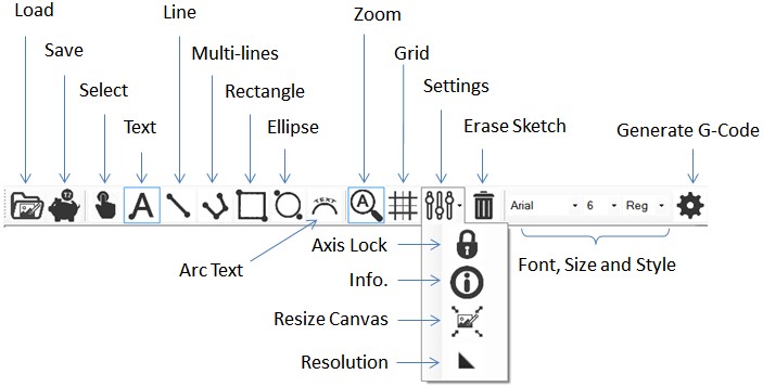
-- Load
- Opens a T2Laser Sketch (.t2s format)
-- Save
- Save the current drawing as a T2Laser Sketch file
-- Select
- Click outline or hold shift key to select inside object
- Click and drag to move or use right mouse button to resize
-- Text
- Click on page at insertion point and type text
- Use pipe | symbol to add a new line between text (or enter text in parameter screen)
- Use select tool to highlight text to change font, size or style
- With text selected
- Press C key to change alignment (left, center and right)
- Press F key to mirror text (flip across vertical axis)
-- Line
- Click start and end points
-- Multi-Line (Polyline)
- Click to add points
- Right click to close the shape
-- Rectangle (or Square)
- Click to start and end rectangle (corners)
-- Ellipse (or Circle)
- Click to start and end ellipse
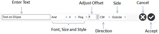
-- Arc Text
- Select an ellipse or circle first and then click the Arc Text icon
- This is a temporary object and can be deleted later
- It can also be used multiple times to add text to the top and bottom as needed
- Enter text and adjust settings (a preview is displayed)
- The parent ellipse rotation will affect the result
- CCW text will appear correct on the bottom or upside down if moved to the top
- Click accept to generate the arc text or cancel to abort (arc text is not generated)
-- Zoom
- Toggle Auto-Zoom (scale to fit)
- Right click to change zoom (1X, 2X and 5X)
-- Grid
- Enable or disable the grid
- Right click to swap between 10 mm and 5 mm spacing
-- Axis Lock
- Lock to X/Y axis or aspect ratio 1:1 for circles and squares
-- Info
- Show or hide the overlay
- Displays document size, magnification, grid size and count of shapes and segments
-- Resize Canvas
- Enlarge or reduce the the Sketch drawing size
- Click the center icon to automatically select the drawing extents
-- Resize (Rescale) Sketch
- Sketch is rescaled to the new size (fonts and arc text may need to be manually edited after rescaling)
-- Resolution
- Resolution used for node/point spacing in ellipses and text
-- Combine Paths
- Automatically joins overlapping paths (use with script style fonts)
-- Erase
- Clears the entire Sketch
-- Font Settings
- Select the Font, Font Size and Font Style
- If text is selected you can scroll through the list to see the result
-- Generate G-Code
- Finish the Sketch and generate the G-Code
- Save the Sketch before exiting (if needed)
- You can return to the Sketch later and save or edit it as required
-- Additional Keys
- Press Delete to erase selected object
- Press L and R to rotate object
- Press F to flip the object (Y-axis)
- Press P to open the parameter entry screen (move or change object)
- Press Ctrl to toggle axis lock
Sketch Plus
-- Modes
- Sketch
- No options selected
- Output as an outline – vector
- Sketch Filled
- Sketch Filled selected
- Output is solid – raster
- Sketch Hatch
- Sketch Filled with a selectable Hatch Pattern (pseudo fill)
- Sketch Plus
- Sketch Plus is selected
- Sketch outline is added to the loaded image – raster + vector
- Sketch Filled Plus
- Sketch Filled and Sketch Plus are selected
- Solid Sketch output is added to the loaded image – raster
- Sketch outline is added to the solid Sketch – raster + vector (no image loaded)
- Trace
- No options selected
- Trace outline is output – vector
- Trace Hatch
- Sketch Hatch is enabled
- Trace is output as a vector with hatch pattern
- Trace Contour
- Sketch Plus selected
- Trace vector is added to the image raster – raster + vector
- Sketch Filled + Sketch Plus
- Text is added in Sketch and combined with image as final raster output
- Sketch Filled + Sketch Plus (no image)
- The text outline is added to filled text (result in a darker crisp edge to the text)
- Trace Contour (using Sketch Plus)
- Vector is shown in red and added to the raster image (used for cutting out the image)
Engraving Modes
- The default mode will auto-detect and use photo mode as needed to improve the results
- Manually selecting photo mode is not recommended especially for clip art / logo engraving
- Unidirectional is significantly slower but allows the laser to cool between lines and reduces "zig-zag" errors on systems with excessive backlash
- Use diagonal mode to improve results with wood grain
- All modes include over-scan on the trailing side to reduce dark edges caused by deceleration
Trace (Raster-to-Vector Conversion)
-- Open Image
- Clipart style high contrast images work the best
- Adjust image and select settings prior to conversion
- Select Trace Image from the tool bar or edit menu
- Click the outline(s) to trace and right click to see just the result
- Turn off trace when complete to generate the G-Code
- G-Code will automatically be generated when clicking Save or Control Laser
- Resize Trace (use the output size button)
- Does not work if hatching is applied, resize the image before tracing if hatch is required
- Do not increase the trace size, instead resize the image and re-trace for improved quality
- Trace Resize (Single Mode) should be enabled for highest detail but can be disabled (see Image Options)
Change Log
-- v1.4j adds crop image feature, auto-crop sketch to extents (sketch + settings), Aussie z-jog, resize "trace" with enhanced detail, beta tester option for updates
--
v1.4k adds Russian and Korean languages, Sketch matrix copy (step and repeat),
file name on G-code header, custom G-code buttons, "splash" screens
added option for CNC Z-Safe height
and depth per pass, aggressive G-code cleaner (automatically correct imported
code), password for beta updates
--
v1.4m tool (pen) change to support EleksDraw or CNC, use spindle speed and
safe Z height for raster CNC mode, fixed "view" for CNC with negative values
Keyboard Shortcuts
-- Design Screen
- Open Image, Ctrl-O
- Import DXF, Ctrl-I
- Import PLT, Ctrl-P
- Save G-Code, Ctrl-S
- New Sketch, Ctrl-N
- Laser Control, Ctrl-L
- About, F1
- Manual, Shift-F1
- Information Overlay, I
- Zoom (Auto), Z
-- Sketch
- Rotate, L and R
- Text Alignment, C
- Flip, F
- Parameter (Edit Mode), P
- Lock Axis, Ctrl
- Information Overlay, I
- Zoom (Auto), Z
-- Laser Controller
- Emergency Stop, ESC
- Jog (Move Axis), Cursor Keys
- Home (Goto), Home Key
-- G-Code Viewer (Simulation)
- Show Origin, G
- Show Frame, F
- Show Dimensions, D
- Start / Stop Simulation, S
- Change Speed, Q
- Show Laser (Off), O
- Show Laser Disabled, B
- Use DXF Power Colors, R
- Laser Width, 0, 1 and 2
Mouse Quick-Clicks
-- Design Screen
- Open Vector, Right click Open Image icon
- Load Sketch, Right click Sketch icon
- Auto Trace, Right click Trace icon
- Show Original Image, Click the Image
- Rapid Feed Rate, Right click the Feed Rate icon
- Relocate Origin, Right click the Relocate Origin menu item for one-time fix
- Optimize DXF, Right click the Optimize DXF menu item for one-time fix
- Save Profiles, Right click to Save Profile
-- Sketch
- Zoom Setting, Right click Zoom Icon
- Grid Size, Right click Grid icon
- Move Object, Click drag on selected object
- Size Object, Right click drag on selected object
-- Laser Controller
- Disconnect, Right click the Emergency Stop button
- Clear Status Messages, Double click the status message window
- Machine Position, Double click the display to switch between machine and workpiece coordinates
- Set Home (Origin), Right click the Home icon (when workpiece coordinates are displayed)
- Home Machine, Right click the Home icon (when machine coordinates are displayed)
- Pause G-code, Press the send envelope while running (press again to resume)
- Save Presets, Right click to save current position as a preset location
- Show Grbl Parameters, Hold the Ctrl-key and click the Home icon to display the Grbl parameters
- Trace Frame, Right click the laser off button
- Engrave Frame, Right click the laser on button
Troubleshooting & FAQ's
-- Why is the laser always on?
- This is likely because of a mismatch between the firmware version (Grbl) and the hardware setting
- Move the jumper under the Nano microprocessor board to the correct location or use the correct firmware
-- Images don't load at the size they were saved?
- The image size is based on the number of pixels and the resolution
- An image 1000 x 1000 px at 0.1 resolution would be 100 x 100 mm
-- How do I "outline" an image?
- An image is a raster format, to cut or engrave it's perimeter you need to convert it to vector by tracing it
- Use the Trace Image or Auto Trace feature in the Edit menu
-- Text isn't importing on vector (DXF) files?
- Text must be exploded or converted to a path before exporting from your CAD program
-- Why aren't my vector (DXF) files filled?
- Vector files are paths only, if you want to "fill" them you need to apply a hatch pattern in the CAD program and save it as a path
-- My sizes aren't coming out correctly?
- If the on-screen size is correct, this is usually because you don't have the correct Grbl parameters loaded
- Use the firmware provided with T2Laser that includes the defaults (currently 1.1e) or click "Send Default Parameters" from the Machine menu
-- How can I improve my grey-scale images?
- The best results require a TTL laser but many non-TTL lasers will provide satisfactory results using the PWM method
- If you are unable to get good results, you can use the "dithered" mode which produces excellent pseudo grey-scale
-- What "mode" should I use?
- For images select grey-scale or dithered, for clip art or logos use black and white mode
-- My laser says "connected" but it isn't working?
- "Connected" means you have opened the COM port, if you don't get a "Grbl Ready" or similar message your laser isn't responding
- Disconnect and verify you have the correct port selected, if so, try uploading the Grbl firmware
-- I don't have any COM ports?
- The COM port is actually a USB driver, check Device Manager for issues (red X) and load the correct driver for your machine
- Most of the Nano clones require the CH34X driver, genuine Arduino Nano's use the FTDI FT232 driver
-- How much does T2Laser cost and where do I get it?
-
T2Laser is trial software, you can download it from
www.t2laser.org and
should test it with your machine before purchasing
-
When you are ready to purchase, a non-transferable single PC license is $39.95
and should be purchased directly from the software
-- I need T2Laser on multiple PC's, do I have to purchase a license for each?
- Yes, we offer 2nd licenses at 20% discount or we have other licensing options available. Please contact us for details
-- How do I upgrade T2Laser?
- T2Laser includes free minor updates for the life of the license
- You will be notified when updates are available and installation is automatic
-- I replaced my computer and now my license key won't work?
- The license is tied to the computer, you will need to purchase a replacement license for the new computer (50% off)
-- I reformatted my computer or replaced the hard drive and now the key isn't recognized?
- If you had to reactivate Windows it is possible Microsoft issued your computer a new ID
- Type "HK" (upper case, without the quotes) in the key code box and provide those hardware values
- If they match your original computer we can generate a replacement key free of charge
Trial Limitations
-- The trial version is for evaluation purposes only, to verify your hardware and this software are compatible and that it meets your requirements
-- Limitations include but are not restricted to
- G-Code and Sketch save is disabled
- G-Code generation is limited to 10,000 lines for raster (1,000 lines for vector)
- Each session is limited to 15 minutes (the program will terminate without warning)
Purchase and Registration
-- All purchases are final and non-refundable, please evaluate it using the trial before purchase
-- The provided license (registration code) is for a single computer (review the EULA for details)
- If you plan to reformat the hard drive or re-load the operating system it is recommended to save the Hardware ID information and send to software@t2laser.org
- Registering unlocks all features, provides free updates and unlimited e-mail support
- To register on the computer you want to license click the PayPal "Buy Now" button
- If you want to register another computer or transfer your license, please e-mail your User ID to sales@t2laser.org
- After payment confirmation we will manually generate and e-mail the key code to register the software - this may take up to 48 hours (it is usually much less)
- Copy/paste the Key Code directly to the box on the registration window
-- Alternate licensing options are available at additional cost
- These include using a licensed Nano or a USB security "dongle" key, contact sales@t2laser.org for details